Input points
The Input Points Tab Page
On this screen the details of all nodes that are input points are entered. Input points are the points in the network where the network is pressurised ie. connected to a water supply or pump. An input node cannot be connected to more than one pipe. If Calculate “Input Point Flow/Pressure” is not being used and a pump is installed drawing water from the mains or a storage tank, it is better to enter the pump as a booster pump.
The input items for input points are:
Node Number
The node number (between 1 and 9999) in the network where the water supply or fire pump is connected.
Elevation
The elevation of the node above or below a given datum in units as specified in the Project Tab Page. If left blank in the Sprinkler and Nozzles, Hydrants/Standpipes or Reference nodes data, the program assumes the default value above the column heading.
Fixed/Curve/Linear/Q185
A selection for:
FIXED A fixed pressure at an input point in which case only Pressure 1 is entered. If the input pressure is not a constant, but a curve (e.g. if the input is a pump, the pressure will drop off as the flow increases), then the curve can be described in one of three ways:
LINEAR signifies a pump or variable water supply pressure being entered as a series of (at least two) points on a curve of pressure vs flow. The program linearly interpolates between the entered points.
CURVE signifies a pump or variable water supply pressure but in this case a series of coefficients are calculated from the entered values of flow and pressure for a polynomial fit to the points. At least eight points must be entered. This is a slightly more accurate method of describing a pump curve than the LINEAR method.
The polynomial takes the form:
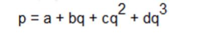
where:
q is the flow and
a, b, c, d are the coefficients which are displayed on the graph and inserted in the input data file for use in the calculations.
- Q185 signifies a variable water supply pressure where the pressure between each pair of entered points is proportional to the flow to the power 1.85.
If the program is calculating the “Input Point Flow/Pressure”, then pressure 1 is used as a first guess for the iterations carried out by the program.
Pressure 1 OR
The fixed pressure available at the imput point in units of pressure as specified in the Job Parameter Screen OR, the shutoff pressure (pressure at no flow) for a pump or variable water supply
Flow 1, Pressure 1, Flow 2, Pressure 2,....Flow n, Pressure n
A series of up to eight flow/pressure points on the pump or water supply curve at the input point. The first value of flow must be zero and the first pressure is the shut off pressure.
If CURVE is being used the number of pairs of points must be eight, and after the first two flows are entered the remaining flows are extrapolated using the same increment for each pair. They may be changed as necessary.
Note that only one pump curve may be described with each input node. If two parallel pumps are present, then:
If the pumps have the same characteristic, enter 2 under number of pumps (only applies if CURVE is used.)
If the pumps have different characteristics, create a second input point close to the first one. Assign to this second input node the same elevation and set of Flow/Pressure values as for the first one.
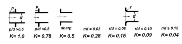
Loss Coeff Tank Exit (FIXED Input only)
When The Input point has a FIXED pressure and this represents the minimum head available from a tank at the input, the user can enter the Loss coefficient of an abrupt exit from the tank. The pressure loss of this fitting is added to the pressure loss of the pipe from the input point (tank).
When linear, curve or Q185 is selected, once sufficient points are entered, a graph appears in the lower portion of the screen displaying the points and the fitted curve. This is a useful check on the entered values and in the case of "curve", whether the curve fit is reasonable. At the right end of the graph there is provision for extending the curve to check, in the case of curve, that the curve behaves acceptably past the last point on the graph.
If a piping network is entered and the pressure at the input point is such that there is insufficient pressure available to ensure a positive discharge through all sprinkler heads or nozzles, the calculation program may iterate to an impractical solution. The usual result, is that the program aborts with the error message:-
WARNING - DH/DQ NOT NEGATIVE - COMBINATION OF PUMP PARAMETERS PROBABLY INCORRECT.
The program can also sometimes end up with negative flows through the sprinklers. It is recommended therefore particularly when using Calculate “Input Point Flow/Pressure” (in which case the entered input pressure is a first estimate only) that the user enters a high value rather than a low value.
Multiple Input Points
When modeling systems with more than one input point, Calculate “Input Point Flow/Pressure” can be used and the program will then determine the flow and pressure at the nominated input point. The other input points must then have an actual characteristic curve or an actual fixed pressure defined. If Booster Pump Flow/Pressure is selected, all input points must have actual characteristics or an actual fixed pressure defined..